

One primary objective of HUVEXEL’s Minimally Invasive Surgery (MIS) is to replicate the clinical results of the corresponding open procedure. The Rexious MIS is the latest spinal fixation system in our MIS system. It has been developed with experienced surgeons’ input to provide efficiency, simplicity and security for MIS procedures. Rexious MIS provides surgeons a low profile fixation solution along with streamlined instrumentation making it simple for the entire OR team to deliver to the patient. Rexious MIS delivers an outstanding system for your MIS procedures.
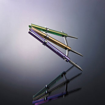
Rexious Mis
The Ring has been designed with efficiency and simplicity in mind to:
- Hold the blades secure while inserting into patient
- Clip in place to maintain its positioning on the blades
- Be low profile to maximize visibility
-
1. Patient Positioning
The Rexious MIS type can be used under local, epidural, spinal, or general synesthesia. General anesthesia is commonly used since it is the most comfortable for the patient and allows immediate postoperative neurological assessment The patient is prepped and draped in the usual sterile manner for posterior fusion with pedicle screw fixation.
-
2. Skin Marking
Using Anterior(A)/Posterior(P) imaging, place a K-Wire across the mid-line of the targeted pedicles.
-
3. K-Wire Insertion
Insert a V-Pin Needle Set through the skin incision to the intersection of the facet and transverse process. Confirm that the V-Pin Needle Set is in the appropriate pedicle starting point determined by using both A/P and lateral images
-
4. Proper Targeting of the Pedicle
- A. Make sure the incision is appropriately placed with consideration of the patient’s anatomy. The larger the patient’s muscle, adipose tissue, and fascia posteriorly, the more lateral the incision.
- B. The V-Pin Needle Set should be “docked” onto the lateral aspect of the pedicle as shown by position 1. This should be confirmed with A/P fluoroscopy.
- C. The Needle of V-Pin Needle Set is advanced 20 to 25mm so that the Needle is beyond the medial border of the pedicle and into the vertebral body, position 2 and position 3.
- D. Use of fluoroscopy can confirm proper placement of the Needle prior to K-Wire insertion. With the Needle in place just past the base of the pedicle, remove the inner stylet of the V-Pin Needle Set. The removal of inner stylet allows the K-Wire to be inserted through the Needle into the pedicle. Caution should be heeded with regard to the position of the K-Wire in order to avoid advancement of the K-Wire too anteriorly. Selectively, Use the V-Pin Needle Set to gain access to the pedicle by advancing the V-Pin Needle Set partially through the pedicle using the Medical Hammer. As the Needle advances through the pedicle, it should approach the medial wall of the pedicle on the A/P images and should approach the base of the pedicle on the lateral images. When the Needle reaches the medial wall on the A/P image, verification must be performed in the lateral image to ensure that the Needle is past the base of the pedicle and starting to enter the vertebral body. The K-Wire Guide Tube can be used to ease insertion of the K-Wire through the Needle and into the pedicle. Advance the K-Wire by hand or use the Medical Hammer to impact the K-Wire in hard bone. Once the K-Wire is inserted, remove the K-Wire Guide Tube, if used, and the outer shaft of the Needle. Take care to hold the K-Wire in position when removing the outer shaft of the Needle.
-
5. Dilation
- A. A. Place Dilator 1 over the K-Wire and down into the incision. Advance Dilator 1 through the soft tissue and lumbodorsal fascia towards the pedicle. Confirm the position of Dilator 1 against the bony anatomy between the facet and the transverse process using imaging.
- B. Slide Dilator 2 over Dilator 1 to penetrate and gently dissect the soft tissue down to the pedicle.
- C. Remove Dilator 1 after inserting and fully seating Dilator 2. Take care to maintain the position of the K-Wire within the pedicle when removing Dilator 1.
- D. Insert Final Dilator over either Dilator 2. With Final Dilator in place, Dilator 2 can be removed. Hold the K-Wire in position when removing the Dilator 2.
- E. We have three different types of Final Dilator. So you can select a desired type of Final Dilator. Three Final Dilators different from the part contacting the bone.
- Dilator 1 : DILATOR, ID1.8 x OD10mm
- Dilator 2: DILATOR, ID10 x OD14mm
- Dilator 3 : DILATOR, ID14 x OD16mm
- Dilator 4 : DILATOR, FULL SPIKE - ID14 x OD16mm
- Dilator 5 : DILATOR, ANGLED SPIKE - ID14 x OD16mm
-
6. Pedicle Preparation
- A. With Final Dilator in place, prepare the pedicle by placing the Cannulated Awl over the K-Wire and insert into the pedicle with a twisting motion. Hold the K-Wire in position when removing the Awl.
- B. The Cannulated Taps are used to further prepare the Screw pathway. The Taps are designed to be used with either Final Dilator for Taps 4.5mm-7.5mm in diameter. The Taps are laser etched with 5mm increments to help indicate the depth of the Tap within the pedicle as well as to help determine proper Screw length.
-
7. Screw Insertion
- A. With the pedicle pathway prepared and proper Screw length, blade length, and diameter determined, prepare the Screw for insertion. Insert the ring in the desired position.
- B. Load Screw onto Cannulated Screw driver First, Hold the Screw by the threaded portion and engage the Inner Shaft into the saddle of the Screw head. Second, fully seat the Inner Shaft into the Screw head and engage the hex of screw. Turn the Outer Shaft clockwise until the threads of the Shaft are fully engaged with the threads of the Screw head. Third, slide the Locking part forward into the Outer Shaft to lock the Screw to the Cannulated Screw driver.
- C. POWER INDICATION NOTE Place the Screw and Cannulated Screw Driver over the K-Wire and advance through Final Dilator to the opening created in the pedicle. Drive the Screw into the pedicle; remove the K-Wire when the tip of the Screw reaches the end of the pedicle to prevent it from advancing. Take care not to insert the Screw too far into the bone, thereby limiting its polyaxial capabilities making it more difficult to pass the Rod during subsequent procedural steps.
-
8. Disengage Cannulated Screw Driver from Screw
- A. Once the Screw is placed: First, depress the button on the Locking part and slide the Locking part back up out of the Outer Shaft along the Inner Shaft.
- B. Second, turn the Outer Shaft counterclockwise to disengage the threads of the Shaft from the threads of the Screw head.
- C. Third, pull upward on the Cannulated Screw Driver. Remove Final Dilator from the wound.
- D. NOTE: The orientation and placement of the Ring can be changed after removal of the Cannulated Screw Driver. Repeat the process for additional Screws.
-
9. Screw Adjustment
- A. The Screw positions may be adjusted as needed using the modular Screw Adjuster. Imaging should be used to confirm desired placement of Screw.
-
10. Using the Caliper, Ball Tip to Determine Rod Length
- A. Pass the ball tips of the Caliper, Ball Tip down through the blades into the screw heads. Simultaneously angle the blades to match the angle of the Indicator arms. Verify the ball tips are fully seated in the screw heads using fluoroscopic imaging or the blade lengths laser markings on the arms. Read the rod length indicated
- B. The design of the Caliper, Ball Tip is optimized to determine the Rod Length over 1 to 2 levels.
-
11. Rod Selection, Contouring, and Insertion
- A. The Rexious MIS type offers a comprehensive selection of MIS Rods. The Rexious MIS type Screw can accept both 5.5mm and 6.0mm rod diameters. The system rods are offered in Titanium Alloy, in pre-bent configurations. This versatility is designed to present various size and stiffness options to meet a spectrum of surgical needs.
- B. The Rod Bender is used to contour the rod as needed.
-
12. Rod Inserter Assembly
- A. Place the end of the Rod into the opening on the distal end of the Rod Inserter. Lock the Rod into position by twisting the knob on the Rod Inserter Shaft clockwise until fully engaged with the Rod.
- B. The Rod Inserter should be disassembled for cleaning. To disassemble, turn the Rod Inserter Shaft counterclockwise. The threaded portion is released pull the Rod Inserter Shaft.
- C. The Rod Insert Driver is used to assemble the rod as needed, instead of turning the knob.
-
13. Inserting the rod and rod inserter
- A. Inserter the rod percutaneously from either the most cephalad or caudal Screw through the blades. Guide the Rod through each pair of blades.
- B. The opening of the Ring at the most cephalad Screw should be oriented in the cephalad direction and the opening of the Ring at the most caudal Screw should be oriented in the caudal direction. The Rod is to be inserted from the open side of the Ring.
- C. Ensure that the Rod overhangs the last Screw head to allow for secure fixation. Also, the hex end of the Rod should not be within the first Screw head.
- D. The positioning of the Rod between the blades can be visualized directly or with fluoroscopic imaging or using the Rod Length/Passage Indicator.
-
14. Set Screw Insertion
- A. Load the Set Screw onto the tip of the Set Screw Driver Guide by engaging the hex.
- B. Slide the Set screw Driver Guide and Set Screw through the Blade and into the blades. Thread the Set Screw, in a clockwise rotation, through the reduction threads of the blades and into the Screw head.
- C. Set Screw and Set Screw Driver Guide will help maintain the open position of the blades. Insert Set Screws into all of the screws.
- D. The Set Screw Driver Guide is intended to be used for final tightening.
-
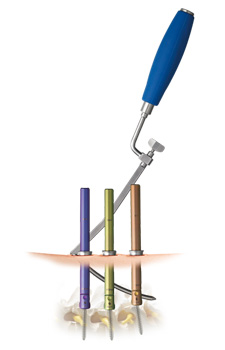
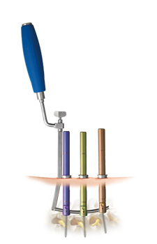
15. Compression and Distraction
The Ring must be removed prior to using the Support Tower.- A. Insert the Support Tower over the blades of the all screws.
- B. The biggest hole on the Support Tower correspond to the blade lengths to indicate when the Support towers are fully seated.
- C. The Pin of the MIS Connector with the notch facing up. Position the MIS Connector in the top hole of the Support Tower.
- D. To distract, insert the Compressor into the eyelets of the support tower and it must be in a position higher than the Support Tower, Squeeze the Compressor to apply the appropriate amount of distraction.
- E. To compress, insert the Compressor into the eyelets of the support tower and it must be in a position lower than the Support Tower, Squeeze the Compressor to apply the appropriate amount of distraction.
-
16. Final Tightening of the Construct
- A. The top of the Support Towers interface with the Anti-Torque A type. The Anti-torque A type can be used, if needed, to apply a downward force on the Support Towers during application of compression or distraction forces top secure the Support Towers in the fully seated position. Anti-torque C type is used as needed instead of Anti-torque A type.
- B. The Anti-Torque A type can be used for final tightening of the Set screws with the Multi-Level Compressor/Distractor in place. The Torque Wrench must be used for final tightening of the construct.
- C. Once the necessary correction procedures have been performed and the spine is fixed in a satisfactory position, the final tightening of the Set Screws is performed using the Anti-Torque A or C type and the Axial Torque set screw.
- D. Insert the Axial Torque set screw through the blades to engage the Set Screw.
- E. Turn the handle of the Torque Wrench clockwise to align the two arrows on the Axial Torque set screw to achieve the 12Nm of torque required to secure the implant construct.
- F. The Anti-Torque A or C type must be used for final tightening. The Anti-Torque performs two important functions:
- 1) It allows the Axial Torque set screw to align with the tightening axis.
- 2) It allows the optimal torque needed to lock each Blocker without applying the torque to the rest of the construct.
- G. Repeat the process for each Set Screw.
- H. Once the necessary compression or distraction is applied and secured by the Set Screws, the MIS Connector assembly can be released from the Support Tower and removed. The Support Tower can then be removed from the blades.
-
17. Blade Removal
- A. Once the construct is finally tightened, the blades can be removed. Slide the Sleeve Cutter.
- B. In the direction of the arrow, apply a force to break the blade off of the Screw head. The Sleeve Cutter will retain the blade within the instrument.
- C. Repeat for the remaining blades.
Copyright © 휴벡셀. All Rights Reserved.